EMI Shielding "Filter" Connectors

About Filter Connectors
Why Filters in a Connector? Theory and Types
If your circuitry is suffering the ill effects of interference from radio waves, stray transmissions, electric power lines or electric motor noise, you are experiencing EMI (electromagnetic interference). This leads the circuit designer to consider EMI filters. A second issue, EMP (electromagnetic pulse) is driven from the catastrophic effects of extremely high voltage, short duration pulses of energy. Traditionally, concern for a nuclear attack was a high priority and now in the military and aerospace environments, protection from lightning strikes and similar high energy sources are a top priority. Protection from this sudden unwanted over-voltage situation is more commonly referred to as TVS (transient voltage suppression).
EMI and EMP are looking for a path to your circuits and that path is usually an antenna or a cable set running to the circuit that is acting as an antenna.
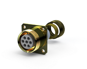
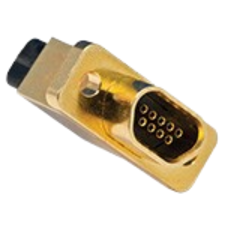
The key warrior against EMI is a capacitor element. Typically, we battle transient voltage with a zener diode. Where is the best place to put these elements? Often military and avionics boxes house the critical circuitry. If the cable set is the antenna then the best placement for the filter is at the cable/box interface, preventing the unwanted signals from entering the system. A multi-pin filter or TVS connector is the ideal solution.
Components for EMI
Most filters are low pass, allowing a signal to pass while eliminating high-frequency noise. In circuit design, two capacitors in parallel running from source to ground, surrounding an inductor in series, is the most effective EMI filter. This is known as a Pi filter (shown below). The advantage of the Pi filter is that it generates the fastest roll-off and highest attenuation levels of any of the popular filter types. The second most popular type, the ‘C’ filter, is comprised of one capacitor element from signal to ground. With fewer components, the ‘C’ filter can often generate the best performance/price ratio.
‘Pi’ filter ‘C’ filter
Other filter types that Amphenol CIT can package include ‘T’ filters, ‘LC’, and ‘CL’. Consult with your Amphenol CIT factory representative for advice on which circuit is best for your application.
Since the connector is the best place for the filter, packaging the ceramic capacitor inside the shell is the design goal. To achieve the maximum filtering performance Amphenol CIT uses planar array capacitors. These monolithic devices have the entire pattern drilled in the ceramic, thus supporting capacitance from signal to ground at every pin in the connector. To build the Pi filter, two arrays are used with a tubular ferromagnetic inductor on every pin (see page 12 for typical connector construction).
Amphenol CIT also filters using off the shelf chip capacitors on printed circuit boards (PCB). This PCB design offers the advantages of lower price at the sacrifice of performance. The attenuation performance will start high at low frequency but will not stay high at higher frequencies, thus demonstrating a ‘knee’ shaped curve. For high-frequency applications, Amphenol CIT recommends planar capacitors construction.
Components for EMP/TVS
Zener diodes are packaged in the Amphenol CIT TVS connectors for a number of applications. On average every commercial aircraft is struck by lightning twice a year. Aircraft are now being designed structurally with up to 50% composite content and have ‘all electric’ flight control systems. Today’s industry standard for lightning testing of electronics is RTCA DO-160, written for conventional aluminum airframes. As such, it may prove lacking for next-generation aircraft. Amphenol CIT designs TVS connectors application specific and meeting industry’s changing requirements. Amphenol CIT Transient Voltage Suppression connectors save space, are lighter, more reliable and more cost-effective than current industry standards. Consult with your Amphenol CIT factory representative for the very latest design technology.
Your application
Meeting your EMI/EMP or TVS needs electrically is only half of the Amphenol CIT SOLUTION. You’ll need the connector to fit and function mechanically as well. With filters housed at the box interface, over 90% of our products are box mount or jam nut receptacle style connectors. This is true for circular connectors as well as our high-end ARINC blind mate filter connectors. In addition, Amphenol CIT provides the customer with exact fits for board mounting PC tail contacts. See page 4 for available contact termination styles.
38999 Qualification
Amphenol CIT designs filter connectors to meet today’s military and commercial connector standards. MIL-DTL-38999 is a ‘gold’ standard for performance in many environments. As applicable, all Amphenol CIT connectors are designed with this level of quality and performance. Today’s aerospace and ground troop applications demand even higher performance. Consult your Amphenol CIT factory representative if your application requires testing above and beyond this standard.


